CB1100 Idle speed instability problem

Dave_imp said:
what i have never been able to work out is how much the difference between the piston and the cyl housing actually is, maybe Dave has an idea, i never asked him back then.
Hi Max. When I inspected my IACV upon removal the piston moved freely within the cylinder housing. If you remember, I even checked the movement of the old IACV versus the new IACV, and I didn't see any difference (checked by plugging it in to the bike normally and turning the ignition key off and on - while watching the piston movement with the IACV removed from the engine). My advice is just replace the IACV. By the way - replacing the IACV completely, 100% cured my idle instability issue, and it has never returned.
[/QUOTE]
Dave, were there any scratches/scoring on the IACV piston, suggesting previous interference from grit or any foreign substance?
 
Lord Popgun_imp said:
The side stand method you posted is right. Also, no one with the problem reported any fault light or codes stored.

How exactly did you connect the probes to the wires? I know, sounds like I don’t have a clue, but if I check mine I want it to be like you did it.
Sorry! I back probed the IACV coils in the ECU connector, today I tried to back probe the IACV connector but almost impossible to fit there a needle. I have my fuel tank out and then I semi install it to get the engine running when needed.
 
It all good. I just lifted the tank a little, removed some panels/covers and removed the connector. A small set of needle nose pliers put the needles in very easily. Then I used a DVOM to make sure they had contact (measured from pin to needle) and plugged it back on the IACV. One needle on each coil "hot" lead (sorry, can't remember the colors right now and the book is at home).

Thing I connected a scope probe to each needle. Then connected the probe grounds together and connected them the negative battery terminal as Max suggested. All was well. Nice 12v pulses.

Speed will post up the videos when he gets them. I sent him 2, but one may have gotten lost in the ether. I may have to resend.
 
Lord Popgun_imp said:
It all good. I just lifted the tank a little, removed some panels/covers and removed the connector. A small set of needle nose pliers put the needles in very easily. Then I used a DVOM to make sure they had contact (measured from pin to needle) and plugged it back on the IACV. One needle on each coil "hot" lead (sorry, can't remember the colors right now and the book is at home).

Thing I connected a scope probe to each needle. Then connected the probe grounds together and connected them the negative battery terminal as Max suggested. All was well. Nice 12v pulses.

Speed will post up the videos when he gets them. I sent him 2, but one may have gotten lost in the ether. I may have to resend.
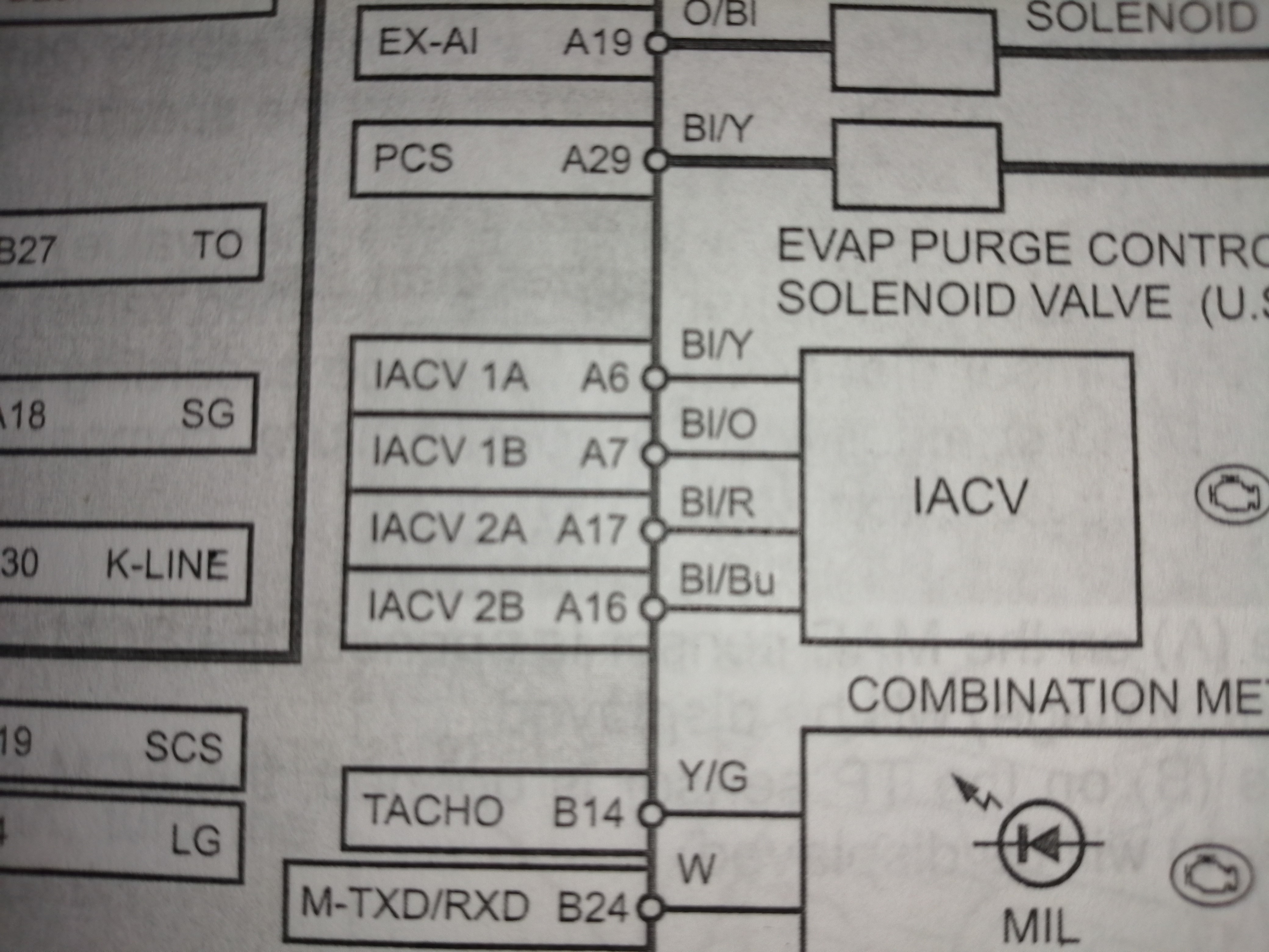
Yes, I received only the 10 seconds video which is very good, nice video of the start up signal. Nice work, I also like the video that Max made (if I am right) with the leds connected. If I connect the probes ythe same way as you did I have the same signal from 0 to 12V, but if I connect the probe to each end of the coil (Bl/Y to Bl/O) I get a signal from -12V to 12V. I am wondering why. By the way, which is the hot lead of the coil? I get 12V pulses coming from both leads of each Coil (Bl/Y to chassis or Bl/O to chassis). Does not matter I disconnect the IACV or not, each lead in reference to chassis ground is getting a 12 V pulse when setting ignition to ON.
 
Here's your stepper motor diagram Speed;


See what happens when you connect a 9v battery across the scope probes and then connect it in reverse, the trace reverts to the centerline instead of remaining in the positive section and the scope makes you think there is a 24v signal, which is why Lord popgun asked you:"how exactly have you connected the probe" meaning: pulses with respect to what? ground or the other side of the coil?.

The windings are reversed because if you reverse the magnetic field you also push the rotor and pull with the other coil.

The use of "the force" is then greater which explains perfectly why we have rlets on our bikes:rofl:
 
I can't say for sure, maybe Max or someone can expose on that, Speed. It would be nice to see a detailed schematic of the ECU and all, but that ain't happening. Could just be the ground reference. I can make some good guesses, but without more info it is kind of pointless. I doubt either of the lines is ground, but rather one line is HI the other LOW, maybe from a differential driver, IDK.

The main purpose of this exercise is to see if your results are the same or different tha a bike that is working. So far they are the same. when measured the same.

I just tried to send you the 5min file, but it is 30.9MB and the mail says it is too big. Anybody have any ideas?

Thanks for that Max! Now I know I should have just put the ground leads on the RLETS :)
 
Lord Popgun_imp said:
I can't say for sure, maybe Max or someone can expose on that, Speed. It would be nice to see a detailed schematic of the ECU and all, but that ain't happening. Could just be the ground reference. I can make some good guesses, but without more info it is kind of pointless. I doubt either of the lines is ground, but rather one line is HI the other LOW, maybe from a differential driver, IDK.

The main purpose of this exercise is to see if your results are the same or different tha a bike that is working. So far they are the same. when measured the same.

I just tried to send you the 5min file, but it is 30.9MB and the mail says it is too big. Anybody have any ideas?

Thanks for that Max! Now I know I should have just put the ground leads on the RLETS :)
Do you and speed have DropBox?
 
max_imp said:
Here's your stepper motor diagram Speed;


See what happens when you connect a 9v battery across the scope probes and then connect it in reverse, the trace reverts to the centerline instead of remaining in the positive section and the scope makes you think there is a 24v signal, which is why Lord popgun asked you:"how exactly have you connected the probe" meaning: pulses with respect to what? ground or the other side of the coil?.

The windings are reversed because if you reverse the magnetic field you also push the rotor and pull with the other coil.

The use of "the force" is then greater which explains perfectly why we have rlets on our bikes:rofl:
Thanks I have been looking for it. So it looks both leads of a same coil are alternatively switching from 12V to ground, it explains why in reference to ground are positive 12V pulses and measuring at the endpoints of each coil (Bl/O to Bl/Y) voltage goes from -12V to 12V which is what the coil is receiving. That is how I measured the signal of the photo

7d1208adf46fd175292933b592493a92.jpg


and measuring between Bl/O and Bl/Y where I can find a 105 Ohm resistance

11f9e581ad41ef4ab61120440e7fc964.jpg


Actually I measured both leads in reference to ground and they both give 12V pulses (alternatively)
Lord Popgun_imp said:
I can't say for sure, maybe Max or someone can expose on that, Speed. It would be nice to see a detailed schematic of the ECU and all, but that ain't happening. Could just be the ground reference. I can make some good guesses, but without more info it is kind of pointless. I doubt either of the lines is ground, but rather one line is HI the other LOW, maybe from a differential driver, IDK.

The main purpose of this exercise is to see if your results are the same or different tha a bike that is working. So far they are the same. when measured the same.

I just tried to send you the 5min file, but it is 30.9MB and the mail says it is too big. Anybody have any ideas?

Thanks for that Max! Now I know I should have just put the ground leads on the RLETS :)
Yes it was the ground reference what was making me crazy, didn't know both leads of a same coil are alternating the 12V output as the rotor of the valve also alternates the poles of the magnets while turning I suppose. You can reduce the size of a video by converting it to MP4 for example in this website: Reduce Video File Size Online, Make Video Smaller (MP4, AVI, MOV, MPEG) | VideoSmaller
SportsterDoc_imp said:
Lord Popgun_imp said:
I can't say for sure, maybe Max or someone can expose on that, Speed. It would be nice to see a detailed schematic of the ECU and all, but that ain't happening. Could just be the ground reference. I can make some good guesses, but without more info it is kind of pointless. I doubt either of the lines is ground, but rather one line is HI the other LOW, maybe from a differential driver, IDK.

The main purpose of this exercise is to see if your results are the same or different tha a bike that is working. So far they are the same. when measured the same.

I just tried to send you the 5min file, but it is 30.9MB and the mail says it is too big. Anybody have any ideas?

Thanks for that Max! Now I know I should have just put the ground leads on the RLETS :)
Do you and speed have DropBox?
I don't have dropbox neither.
 
Thanks Speed, yes this reversal can get you confused so i thought a diagram would help to explain how and why this happens.

Would it be an idea to pm L.P. with your login details for your youtube channel so he can login and post it side by side?
 
I’ll look into the videosmaller thing, Speed. Right now I’m waiting for it upload to the iCloud so I can mess with it on my iPad or MacBook. Much easier than the phone. Only the 10 second one has shown up so far.

In the meantime I’ll going out in the garage and see what happens when I open the throttle gently. The video for that should be pretty small.

I’
 
I don’t use iCloud, but you may be able to give access to someone to download a file. Microsoft OneDrive or Google Drive would a allow it.
 
Cormanus, I don’t know how to do that, if its possible. The smaller thing looks pretty easy though.

You may not use iCloud, but your devices are using it. Holds backups, copies of your pics, music, etc. Its how you take a pic on, say, your phone and it shows up on your MacBook and iPad.
 
Popgun, I’ll send you an email.
 
L.P. you can usually create a clickable link to any web page you are on by;

Double clicking on the browser ip-adress window ( with the http etc in it ),which then highlights ( changes color ) and right clicking on the highlighted text and leftclick "copy" , you can then open a message like this and "paste" the link into the message, it will show as a red clickable link in the message like this;
CB1100 Idle speed instability problem

When anybody clicks on it they will open a new window and go to that webpage the link was obtained from.

You probably already know this but just in case....

Ill now go back into my little corner and be quiet again.
 
I've just had a bit of a hunt around iCloud, my lord Popgun and I think I can help you make it work.

Max, your method will work with many web pages, but it may not (probably should not) work with a link to a file in cloud storage if it's protected. It looks possible to give people permission to access files stored in iCloud Drive.
 
Lord Popgun_imp said:
I’ll look into the videosmaller thing, Speed. Right now I’m waiting for it upload to the iCloud so I can mess with it on my iPad or MacBook. Much easier than the phone. Only the 10 second one has shown up so far.

In the meantime I’ll going out in the garage and see what happens when I open the throttle gently. The video for that should be pretty small.

I’
Yes it is clear, working as designed, thanks Popgun. The only thing is that while engine running a pulse train appears when opening the throttle that lowers the idle speed. This video is clue to understand what happens to my bike, specially at 0:35 very clear.

 
Max, thanks. That I knew. I don’t know how to make a WORD a link. Like, click on WORD and it goes somewhere. I guess it isn’t hard as everybody does it.

Meanwhile back to the issue at hand.

I started the bike and let it warm up to 1100rpm. Was fun watching the ECU issue a pulse or 2 every now and then and seeing the RPM needle fall a little. If I had the diagnostic tool running I could watch the step count too.

Anyway, after it warmed, I did the gently open the throttle thing. The IACV would receive a small pulse train of around 4 pulses as it came off idle. A time or two I did not see anything. But mostly I did. I didn’t video it yet, wanted to see what would happen first.
 
Speed_imp said:
Lord Popgun_imp said:
I’ll look into the videosmaller thing, Speed. Right now I’m waiting for it upload to the iCloud so I can mess with it on my iPad or MacBook. Much easier than the phone. Only the 10 second one has shown up so far.

In the meantime I’ll going out in the garage and see what happens when I open the throttle gently. The video for that should be pretty small.

I’
Yes it is clear, working as designed, thanks Popgun. The only thing is that while engine running a pulse train appears when opening the throttle that lowers the idle speed. This video is clue to understand what happens to my bike, specially at 0:35 very clear.

I would not expect the idle air control valve to have much effect once the throttlebody(ies) opens.

It sounds as though the fuel injectors are not compensating properly for the throttle bodies opening.

One possibility is an incorrect setting on the throttle position sensor...hence the TPS is not properly informing the ECM of the throttle position.

If that is the case, the first step would do a TPS reset procedure and if that has no effect, then follow the manual instructions for checking the voltage for TPS fully closed and fully opened.

tps evaluating for ii issues

http://cb1100forum.com/forum/showthread....20&page=66

Post 651: A, B & C

From post 617 in this thread

These are basic TPS checks condensed from FSM 5-23 and 5-24 (no Honda MCS diagnostic instrument needed):

DTC 8-1 TP (Throttle Position) sensor low voltage
With ignition switch on and stop/run on, probe sensor contacts to verify steady voltage increase from throttle fully closed to throttle fully open.
With ignition switch off, disconnect the connector, then with ignition switch on and stop/run on, measure voltage between connector pins black/yellow (+) to black/green (-) for 4.75 to 5.25 vdc.
If no voltage, with ignition off, check continuity on black/yellow to ECM connector, for continuity of center pin sensor output black/red wire to ECM connector and for no continuity (infinity) of black/red wire to ground.

DTC 8-2 TP (Throttle Position) sensor high voltage
With ignition switch off, disconnect the connector, measure sensor resistance between black/red and black green of 0.5 to 1.5 K ohms. Then with ignition switch on and stop/run on, measure voltage between connector pins black/yellow (+) to black/green (-) for 4.75 to 5.25 vdc.
 
Finally I uploaded to my channel the video Lord Popgun made with the control signal from the ECU to the IACV valve from his known good idle speed adjustment bike. Engine sound can be heard also so you can make yourself an idea of what is happening, and with both channels to monitor the signal of each one of the coils. I love it! Thanks man! With that I can definately rule out the ECU is screwed, my control signals are as expected, so there is only one way for me to go for repairing it. Yes. Replacing the IACV!! I will, keep you posted. This is the link to the video Lord Popgun made:

SportsterDoc_imp said:
Speed_imp said:
Lord Popgun_imp said:
I’ll look into the videosmaller thing, Speed. Right now I’m waiting for it upload to the iCloud so I can mess with it on my iPad or MacBook. Much easier than the phone. Only the 10 second one has shown up so far.

In the meantime I’ll going out in the garage and see what happens when I open the throttle gently. The video for that should be pretty small.

I’
Yes it is clear, working as designed, thanks Popgun. The only thing is that while engine running a pulse train appears when opening the throttle that lowers the idle speed. This video is clue to understand what happens to my bike, specially at 0:35 very clear.

I would not expect the idle air control valve to have much effect once the throttlebody(ies) opens.

It sounds as though the fuel injectors are not compensating properly for the throttle bodies opening.

One possibility is an incorrect setting on the throttle position sensor...hence the TPS is not properly informing the ECM of the throttle position.

If that is the case, the first step would do a TPS reset procedure and if that has no effect, then follow the manual instructions for checking the voltage for TPS fully closed and fully opened.

tps evaluating for ii issues

http://cb1100forum.com/forum/showthread....20&page=66

Post 651: A, B & C

From post 617 in this thread

These are basic TPS checks condensed from FSM 5-23 and 5-24 (no Honda MCS diagnostic instrument needed):

DTC 8-1 TP (Throttle Position) sensor low voltage
With ignition switch on and stop/run on, probe sensor contacts to verify steady voltage increase from throttle fully closed to throttle fully open.
With ignition switch off, disconnect the connector, then with ignition switch on and stop/run on, measure voltage between connector pins black/yellow (+) to black/green (-) for 4.75 to 5.25 vdc.
If no voltage, with ignition off, check continuity on black/yellow to ECM connector, for continuity of center pin sensor output black/red wire to ECM connector and for no continuity (infinity) of black/red wire to ground.

DTC 8-2 TP (Throttle Position) sensor high voltage
With ignition switch off, disconnect the connector, measure sensor resistance between black/red and black green of 0.5 to 1.5 K ohms. Then with ignition switch on and stop/run on, measure voltage between connector pins black/yellow (+) to black/green (-) for 4.75 to 5.25 vdc.

I would not expect the idle air control valve to have much effect once the throttlebody(ies) opens.

It sounds as though the fuel injectors are not compensating properly for the throttle bodies opening.

One possibility is an incorrect setting on the throttle position sensor...hence the TPS is not properly informing the ECM of the throttle position.

If that is the case, the first step would do a TPS reset procedure and if that has no effect, then follow the manual instructions for checking the voltage for TPS fully closed and fully opened.

[url=http://cb1100forum.com/forum/showthread.php?tid=11984&highlight=Tps+reset]http://cb1100forum.com/forum/showthread.php?tid=11984&highlight=Tps+reset


http://cb1100forum.com/forum/showthread....20&page=66

Post 651: A, B & C

From post 617 in this thread

These are basic TPS checks condensed from FSM 5-23 and 5-24 (no Honda MCS diagnostic instrument needed):

DTC 8-1 TP (Throttle Position) sensor low voltage
With ignition switch on and stop/run on, probe sensor contacts to verify steady voltage increase from throttle fully closed to throttle fully open.
With ignition switch off, disconnect the connector, then with ignition switch on and stop/run on, measure voltage between connector pins black/yellow (+) to black/green (-) for 4.75 to 5.25 vdc.
If no voltage, with ignition off, check continuity on black/yellow to ECM connector, for continuity of center pin sensor output black/red wire to ECM connector and for no continuity (infinity) of black/red wire to ground.

DTC 8-2 TP (Throttle Position) sensor high voltage
With ignition switch off, disconnect the connector, measure sensor resistance between black/red and black green of 0.5 to 1.5 K ohms. Then with ignition switch on and stop/run on, measure voltage between connector pins black/yellow (+) to black/green (-) for 4.75 to 5.25 vdc.
I checked the values of resistance and voltage of the TP sensor and they are within specs. Resistance rising up evenly while opening throttle. If I disconnect the TP sensor (which I did minutes ago) the MIL light goes on and disables the operation of the IACV, no signal to it, then I don't have low idle issues. If I disconnect the IACV I dont have low idle issues also. I am pretty shure the TP sensor is OK, ruled out. And ECU also ruled out, I only can try with a Software update before starting the IACV replacement. Ouch!
 
Back
Top