I screwed up big time....

Good point jtopiso, we know that one ecu has survived a polarity change ( the 20A fuse operated ) so that is good news.

Several years ago i had no idea how fuel injected engines worked, i got interested and have learned some things,
turns out it was not all that difficult after all, the trick is not to get mesmerized by too many sensors, just look at one at a time.

It all starts with the crankshaft sensor, it basically is a switch, as the crankshaft rotates the ecu recognizes the gap in the teeth, realizes that is top dead center, resets itself to zero and then starts counting the teeth; it is programmed to fire on the second tooth and inject on the fourth tooth
( i made the numbers up but the principle is the same )
Not too dissimilar to old style contact points;


So then the ecu is programmed to fire the injection and the ignition coils respectively as it counts the teeth on the ckp sensor;


So in this case you can forget about all the other stuff on the bike ( except for the fuel pump ) because you proved it runs fine with starter fluid and just make sure the basics are working as they should.
No point in replacing a lot of parts if the injector supply is not correct, it will never work unless you diagnose the actual cause.

Hope this helps to simplify things, have a quiet coffee and make a plan, if you can work out camshafts you can definitely handle this, we are looking over your shoulder.....
 
Thread starter
jtopiso_imp said:
I'd start checking if voltage arrives at the fuel pump with/without the killswitch (or just have someone listen: contact on and kill switch on/off and you can hear the fuelpump working for a second when you swith to "on").

I wouldn't be surprised if there is extra protecction not to allow a melting wire inside the fuel tank, so I'd check that circuit first.

The harness shouldn't be the weakest point on any installation: no matter what you connect it to. Fuses (or some components acting as fuses) are there to prevent wires to get too hot and avoid fires. So I don't think you'll find a melted wire. But I've been wrong before...

The noise is there even when the tank is removed- so something else 'primes' when the key is turned- I just don't know what. You hear the relay click- and something goes bbrrrrrr for a couple seconds.

I saw smoke and heard sizzling around the battery area- but opened both the power commander and the autotune box and saw no visible damage or sign of heat.

Fuses are typically on + wires- to prevent over current. Reverse polarity is different- sending power in places it was never intended to go.


I'll check the 12v to injector when I get home from work this afternoon.
 
Great post Max and very measured. As an example of the benefits of Max's methodology in action. The crankcase position sensor is a known weak point on the 90's era Triumphs and it has fooled many a skilled man in to tearing down carbs, changing the HT leads, spark plugs, checking valve clearances, swapping coils, you name it. The shame was it was easy to get to and easy to test with a $10 multi-meter, it was also quite a low cost item to replace. If only they had started right at the root as per Max's diagram.
 
Thread starter
max_imp said:
Dubs you may have already checked this but do you have 12 volts on all four black/white wires on the fuel injectors?
They are fed from the +12 volt " fuel cut" relay.
just unclip one and check for 12 volts on the black/white wire with ignition and killswitch on.

They get pulled to ground by the ecu and have back-emf diode protection in the ecu circuit across the transistors/fet's.
If the ignition switch was off the ecu had no power and was only connected to ground and the controlling injector circuits should not be damaged because they were not activated.

Good job with the starter fluid, divides the problem in two parts right there, golden.

Do you have a circuit diagram to work things out?


Confirmed yes, on one of them. Any need to do all 4?
jtopiso_imp said:
I'd start checking if voltage arrives at the fuel pump with/without the killswitch (or just have someone listen: contact on and kill switch on/off and you can hear the fuelpump working for a second when you swith to "on").

I wouldn't be surprised if there is extra protecction not to allow a melting wire inside the fuel tank, so I'd check that circuit first.

The harness shouldn't be the weakest point on any installation: no matter what you connect it to. Fuses (or some components acting as fuses) are there to prevent wires to get too hot and avoid fires. So I don't think you'll find a melted wire. But I've been wrong before...


Any know off the top of their head which wire at the connector where the fuel pump plugs in at the side of the airbox?

I have already gouged my hand getting the tank disconnect off- so would rather not try to test at the tank itself.
 
Thanks for checking, the diagram shows a brown wire for the 12v feed to the pump.
Keep in mind that this only supplies 12v for a second ( to prime the fuel pressure )and then waits for the engine to run before constant 12v supply is provided to the pump through the fuel-cut relay.
best to connect a 12v light between brown and green ( 3 pole connector ) or green/black ( 4 pole connector ) wires and watch it when the ignition is switched on.

Same for fuel injectors, i would check both outside fuel injector connectors with a 12v test light rather than a meter, that way you know the supply is reliable with a load attached, a 20 watt lamp is perfect for this job.

If you could provide a circuit diagram of how the commander etc. is wired that would help a lot, as far as i can work it out you unplug the 10 pole connector for the injectors and insert the p.com in between these connectors?
 
Thanks, just thinking ahead; the pcv only connects to the neg 12v terminal ( for the injector control ) so connecting it to 12v pos would do no harm to the injectors.

But as i understand the pcv also connects to the tps on the side of the throttle body, the tps is also connected to ground at one of the 3 pins ( the black/green wire ) so putting 12v pos on this wire could produce smoke, it would normally set a fault code but who knows in this case?

according to my wiring diagram the tps ground runs from the tps through the 10 pole connector, changes to a green/orange wire and then connects to the common SIGNAL GROUND like all the green/orange wires do, this means there is no load current flowing through these wires and they are a small diameter as opposed th the GREEN wires which are load ( current ) carrying , they just are connected to one single point on the chassis under the tank.

I could well be wrong on this but without looking at it myself this is my best guess.

I would think this green/orange wire could have suffered a current overload, check with a 20 watt lamp connected to 12v pos if this is the case, thanks for the pdf.

Edit; the can interconnect cable also has a ground wire incorporated, does this look as if it has been overloaded?
 
Thread starter
Remember- the screw up was putting +12 to the ground of the autotune- which itself plugs into the power commander on an acc port.

So without schematics on both of them- we can only guess.


As for what all you just suggested- sorry but it all scrambled in my head as I read it and I made no sense out of it.

There is only 1 plug on the power commander so unless it feeds off to the TPS on the same 10 plug...
 
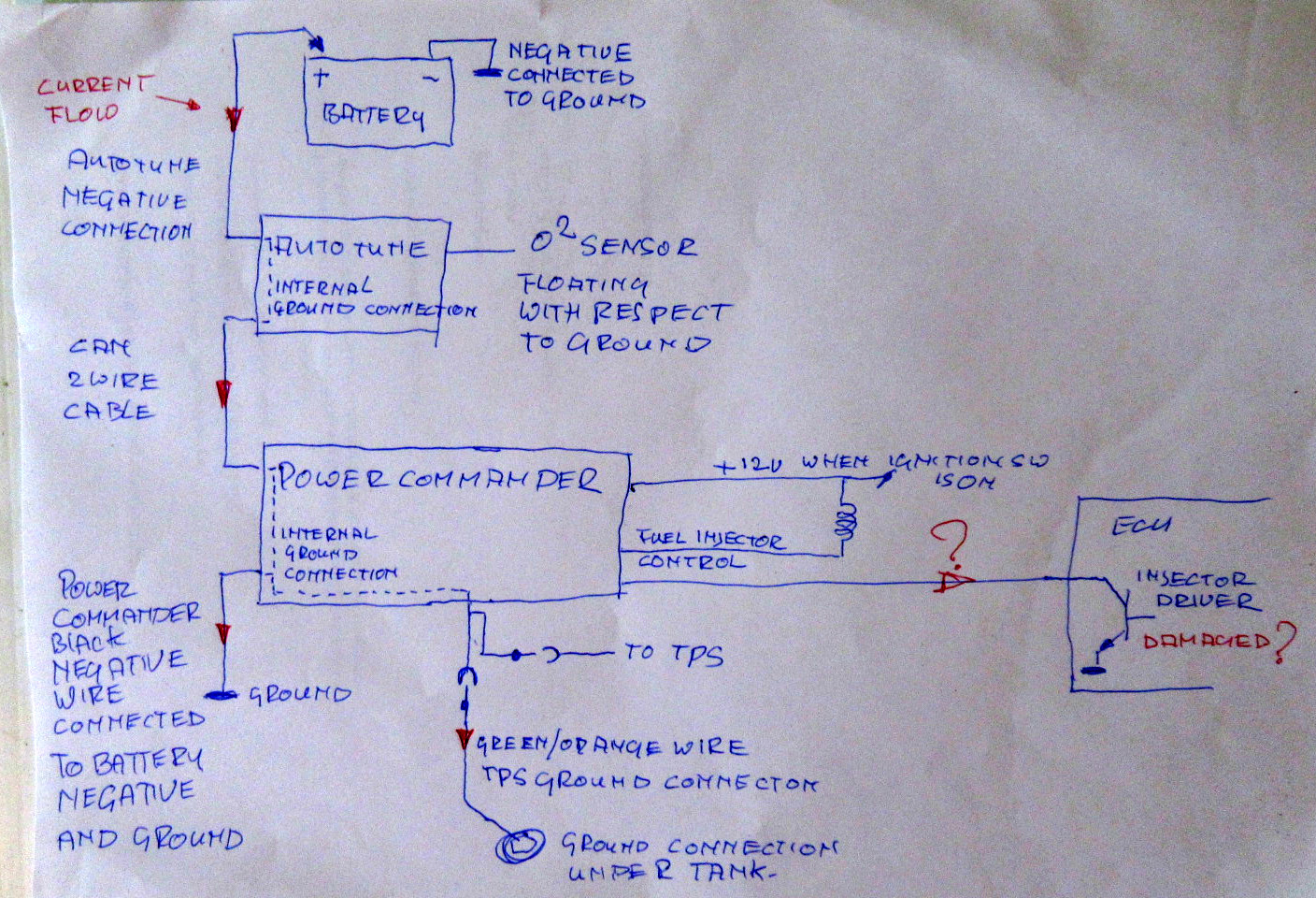
time for another diagram;

After watching several yt video's and two pdf docs i distilled this diagram as best i can;

click on the picture for a bigger version.

4741beff888da77df35f5f49b25e853e.jpg


Here is a diagram in which the fault current is shown in the red arrows flowing from the battery positive through the autotune via ground connection of the can cable to the pcv, through the pcv's internal ground path to;

1 the pcv ground connection to the battery
2 the tps green/orange ground connection ( but not through the tps itself )
3 possibly through the pcv injector input which is the ecu driver circuit for the injector.

If the ignition switch was off at the time of the fault this would not cause a fault because the transistor was not pulled low to ground but open and unable to pass current.

And yes, the tps is included in the 10 pole connector and used by the pcv to know how far the throttle is opened and adjust the fuel injector timing as Part of the map input according to what i understand.
 
Thread starter
max_imp said:
Thanks for checking, the diagram shows a brown wire for the 12v feed to the pump.
Keep in mind that this only supplies 12v for a second ( to prime the fuel pressure )and then waits for the engine to run before constant 12v supply is provided to the pump through the fuel-cut relay.
best to connect a 12v light between brown and green ( 3 pole connector ) or green/black ( 4 pole connector ) wires and watch it when the ignition is switched on.

Same for fuel injectors, i would check both outside fuel injector connectors with a 12v test light rather than a meter, that way you know the supply is reliable with a load attached, a 20 watt lamp is perfect for this job.

If you could provide a circuit diagram of how the commander etc. is wired that would help a lot, as far as i can work it out you unplug the 10 pole connector for the injectors and insert the p.com in between these connectors?


OK so back in the garage now and first thing I did was go to the brown wire at the disconnect on the side of the airbox and checked – yes I have momentary 12 V there when I turn the key on.

And then for fun I went to test the outside injector on the other side.

Yesterday with my wife standing here I pulled off the left side injector disconnect, put my meter on the black and white wire and the other end on ground, turn the meter on and then turn on the bike ignition and got 12 V.

Today when I went to do the right side injector as soon as I touched my positive meter lead to the black and white wire- my meter switched to a continuity beep to ground.

What the?

It did not do that yesterday.

So I went back just now to the left injector and tried what I did yesterday again but sure enough the black-and-white wire has continuity to chassis ground and the bike is turned off.


Sent from my iPhone using Tapatalk
So since somehow now the black and white wire appears shorted to chassis, I unplugged one of the ECU connectors and it’s still beeped. Plugged it back in, then unplugged the other connector and it’s still beat. But if I unplug both of the connectors it stops.


Sent from my iPhone using Tapatalk
 
And that's correct, all the equipment is connected to the same 12v " bus " at the load end of the fuel cut relay and that is what you are checking with the ohm meter, we are learning.

If you told me to take out the camshafts and grind 0.2 mm of one lobe i would have the same difficulty understanding.:huh:

The real test is to take a 20w lamp and see if the two outside injectors have 12v AND make the lamp go on.

The reason for using the lamp is to make sure the wire can supply enough current when the injector is energized, the meter will indicate 12v just fine even with a bad connection because it draws very little current by design, same as testing a knot in a rope by giving it a good tug making sure it holds the load.

Thanks for the test with the brown pump supply, that sounds good.:thumbsup:
 
Thread starter
I am confused. So I should not be concerned that the black and white wire to the injector has continuity to the frame?

If the 12 V can already go right to the frame without even being attached to the injector then why would it bother to pass through the injector on the other side?

Thank you for all your time!

And double thank you for your patience with someone like me that has no idea how the electronics of all this stuff works.


Sent from my iPhone using Tapatalk
I am looking at the 10 plug harness that the power commander goes into, do not see a green and orange wire, just unplug the TPS sensor and looked there and again no green and orange wire.

My bike is a 2014 US model.


Sent from my iPhone using Tapatalk
 
PowerDubs_imp said:
I am confused. So I should not be concerned that the black and white wire to the injector has continuity to the frame?

If the 12 V can already go right to the frame without even being attached to the injector then why would it bother to pass through the injector on the other side?

Thank you for all your time!

And double thank you for your patience with someone like me that has no idea how the electronics of all this stuff works.


Sent from my iPhone using Tapatalk
I am looking at the 10 plug harness that the power commander goes into, do not see a green and orange wire, just unplug the TPS sensor and looked there and again no green and orange wire.

My bike is a 2014 US model.


Sent from my iPhone using Tapatalk
 
Thread starter
OK so went back to the injector again and turned it on and got 12 V at each side outside injectors when ignition is turned on. Oddly enough once I turn the key back off and the 12 V goes away the meter does not go back to a continuity beep unless I take my probe off and then touch it again.


Sent from my iPhone using Tapatalk
max_imp said:
PowerDubs_imp said:
I am confused. So I should not be concerned that the black and white wire to the injector has continuity to the frame?

If the 12 V can already go right to the frame without even being attached to the injector then why would it bother to pass through the injector on the other side?

Thank you for all your time!

And double thank you for your patience with someone like me that has no idea how the electronics of all this stuff works.


Sent from my iPhone using Tapatalk
I am looking at the 10 plug harness that the power commander goes into, do not see a green and orange wire, just unplug the TPS sensor and looked there and again no green and orange wire.

My bike is a 2014 US model.


Sent from my iPhone using Tapatalk


That’s what my wife says.

You should’ve seen the look on her face the other day when I said “I have to get my bike fixed so I can put it on my dyno”

She is quick enough that she noticed I said “my dyno” and not “the dyno”.

6583522b0417cbd6c774fc4fee949289.png


So I am at the TPS plug and yes there is a black and green wire. Just for fun I checked and it also goes continuity to frame.

I found the green and orange, I was looking at one end of the 10 pin connector that comes out from the ECU area and not the other side.

So now that I found it on the 10 pin connector up on the main harness above the cylinder head cover what am I doing with that?


Sent from my iPhone using Tapatalk
Green orange wire at far end of 10 connector also confirmed grounded to chassis continuity.


Sent from my iPhone using Tapatalk
The Orange and green at the ten pin must be the direction the ground is in because if I disconnect that I lose ground at the other side of the 10 pin and at the TPS itself.


Sent from my iPhone using Tapatalk
 
Are there any fault codes from the orange cel indicator?

If not i would remove THE NEGATIVE TERMINAL of the battery, let the ecu settle down, put the tank back on,( careful with that fuel connector ) re-connect the battery when all connectors are plugged back in and try again, keep the starter fluid handy just in case.

I have had it in the past that the engine would not fire after sitting for a few days and after a little brake cleaner it just went back to normal:huh:
 
Thread starter
SOOO….. pulled the negative. Waited a minute, reattached.

I put the tank back on- flipped the switch, heard the fuel pump- hit the start button and it fired right up like nothing ever happened.

88aa29a47f9efc1c1dbdda3b40fa77b0.png


Sent from my iPhone using Tapatalk
 
PowerDubs_imp said:
SOOO….. pulled the negative. Waited a minute, reattached.

I put the tank back on- flipped the switch, heard the fuel pump- hit the start button and it fired right up like nothing ever happened.

88aa29a47f9efc1c1dbdda3b40fa77b0.png


Sent from my iPhone using Tapatalk
That is really good news PD. :banana:
 
Thread starter
Tomorrow I’m going to tempt fate and put the power commander back in.

Before I took it out- I plugged my computer cart into it- and it acted normal- could pull the map, and no errors (it has a drop down menu for error checks)

So I figure if anything is fried- it is probably the autotune box.


Sent from my iPhone using Tapatalk
 
What; no new ecu, no new harness?
What happened?

Can't help myself sometimes Josh, nice outcome and if it was me i would leave it for a week and think things over.:)
 
Back
Top