
the Ferret
Road warrior
Peter a std would have one pipe this one 02 sensor.
Hey I was able to contibute to this thread..woo hoo
Now back to the smart guys
Hey I was able to contibute to this thread..woo hoo
Now back to the smart guys
Follow along with the video below to see how to install our site as a web app on your home screen.
Note: This feature may not be available in some browsers.


That's what I thought but wanted to be 102% sure..and is like our CDN bikes 2013-16 as far as muffler/02 sensor is concernedThe ferret_imp said:Peter a std would have one pipe this one 02 sensor.
Hey I was able to contibute to this thread..woo hoo
Now back to the smart guys

THANKS for the thread, perfect VIN deciphering..Cormanus_imp said:Now help me again, Peter, please. What is VSS?
The VIN thread is http://cb1100forum.com/forum/showthread.php?tid=10637






Couple of pictures would be nice to get us startedSearcher_imp said:Does anyone know the functions on the right , small ribbon cable in the meter assembly (left side when facing headlight from in front of bike). This is for a 2014 standard. I broke the female connector on the little circuit board in a crash and the bike seems to run fine without it being connected except for no tach. Are there any other functions controlled by this little ribbon cable? I'm not an electrical guy so I am not really able to read the schematic in the manual too well. I don't want to damage the bike. Is the thermister controlled by this little cable? Any other functions that could damage the bike if not connected?
Couple of pictures would be nice to get us startedmax_imp said:Couple of pictures would be nice to get us startedSearcher_imp said:Does anyone know the functions on the right , small ribbon cable in the meter assembly (left side when facing headlight from in front of bike). This is for a 2014 standard. I broke the female connector on the little circuit board in a crash and the bike seems to run fine without it being connected except for no tach. Are there any other functions controlled by this little ribbon cable? I'm not an electrical guy so I am not really able to read the schematic in the manual too well. I don't want to damage the bike. Is the thermister controlled by this little cable? Any other functions that could damage the bike if not connected?
Thanks Max. I didn't know you could replace the individual pins in the female connector on the circuit board. I was going to try to get the whole female connector from digi-key or somewhere using those photos and the measurements of the male connector on the ribbon cable, then try to find someone to install it after removing the broken one on the circuit board. The entire "meter assembly" is $600 (parts not sold separately).max_imp said:Thanks searcher, from what i can see the white cable with the one red wire seems to be an interconnect between the left and right part of the cluster or an inter connect for the display.
It seems salvageable but you need to dis-assemble the pcb to get access to the back of it and re-connect the missing? pins, someone with good eyes and soldering iron and some knowledge can probably do some good here, even if he needs to make some pins and solder short wires to what is left of the electrical tracks on the back of the connector pins one by one.
Dont try to connect only part of the connector, all of these wires must be connected at the same time.
I would leave the connector in tact as it is for the future and to keep the white wires in order since they all look the same when you get them out of the connector, just push some new pins in the connector holes or repair the pins in the board.
There is no harm in running the bike in the situation it is in now, the cluster only receives signals from various parts of the bike and processes some of them.
The connector behind the broken one with the colored wires is likely from the headlight and is shown on the pdf in the left top corner.
If you mean the oil temperature sensor by " the thermistor " no, the ot sensor is directly connected to the electronic control module under the tank, see diagram.
cheers; max

Thanks. That will be a lot better than spending $600 for a new meter assembly. Removing the circuit board looks easy. Finding someone to do the work is harder. I asked a commercial company that repairs electronic boards for a friend's company and they said they wouldn't touch it because it was for a motorcycle.max_imp said:Although it is not clear from the photo i think most if not all of the pins ( male connector on pcb ) are still there, if any are missing it would be a simple task to replace the missing/damaged beyond repair pins with cut to size resistor leads that fit well into the female ribbon connector and bend all pins straight again, they are just tinned copper, just have a good look at broken soldering joints at the connector on the pcb.
It may be better to repair the existing connector because of the risk of damaging the tracks with heat during replacement, there is likely enough friction to keep the connector in place despite the plastic not being able to capture the cable connector in place.
Was this mod done to a 2014 model or a 2013?911jimmy_imp said:Hey guys so sorry it has taken me so long to get back but wanted you all to know that the 13 ECU WAS plug and PLAY with the 2014 CB1100 harness .
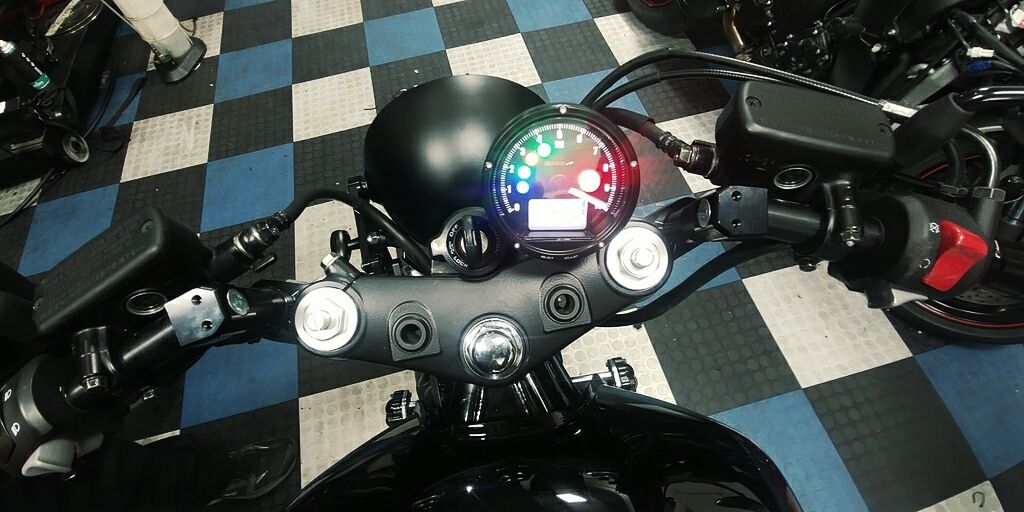
We we're able to complete the build with the KOSO TNT gauge and it came out so amazing .. ONE weird thing is NEUTRAL light tends to be a little intermittent with the KOSO GAUGE..
You have to rev the engine to 5k and the light stays solid (koso) or if you pull the clutch in it reads perfectly . Trying to wrap our brains around it but the owner of the bike wasn't bothered much .
AGAIN THANK U ALL SO MUCH!
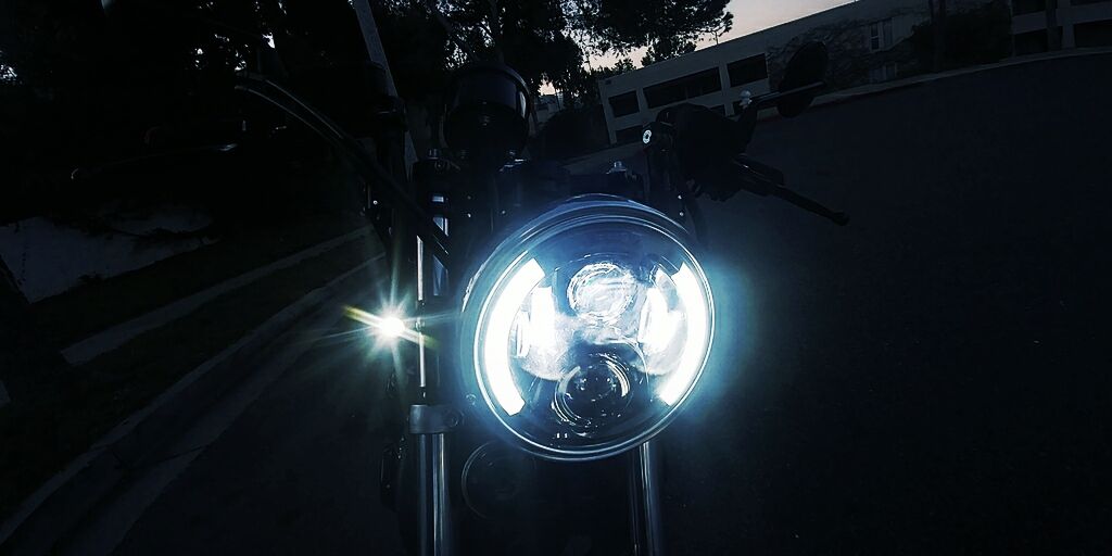
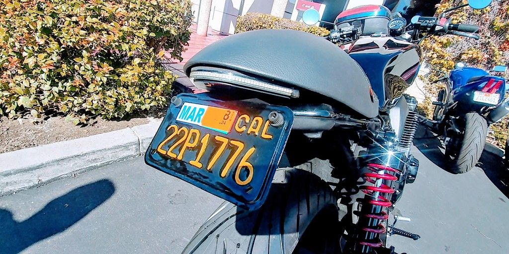
JIMMY SUMMERS (here are updated photos)


